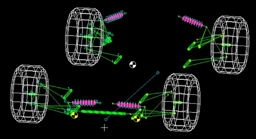
KINEMATICS & VEHICLE DYNAMICS
DELIVERING THE GRIP
THE CAR
DEMANDS.
"Suspension design is a constant trade-off. You cannot optimize every parameter at once. Some gains demand compromises. We choose what matters most, accept the sacrifices, and engineer the best possible balance—because in this domain, the 'best of both worlds' does not exist."
THE MATH OF
MECHANICAL GRIP
"In motorsports, horsepower is useless without mechanical grip. The suspension system and tyre selection determine exactly how much lateral and longitudinal force the car can safely withstand during a lap, which ultimately dictates our lap times."
THE BOLD MOVE:
ZERO ARBs
"We made the strategic decision to completely eliminate both front and rear Anti-Roll Bars (ARBs). This approach drastically simplified our packaging, reduced component complexity, and allowed us to shed significant weight without compromising dynamic stability or suspension performance."
01 // THE OBJECTIVE
Maintain strict 65 kg unsprung mass while optimizing dynamic camber & bump steer. Strategic elimination of all ARBs — simplified packaging, reduced complexity.
Lotus Shark · SolidWorks · ANSYS FEA · Excel
02 // GEOMETRY SHIFT
A-Arm inclination: 99° → 105°. Front IC closer to wheel, shortened FVSA. Result: 45% increase in dynamic camber with bump vs. previous prototype.
FOS validated · Topology-optimized · Zero compliance · Clearance for packaging
03 // MATERIALS
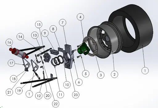
A-Arms: AISI 1018 Steel — strength, weldability. Uprights/Hubs: Al 7075 T6 — high strength-to-weight, fatigue life.
Validated: Lotus Shark · ANSYS FEA · Driver feedback
SUBASSEMBLY NOMENCLATURE
& MATERIALS
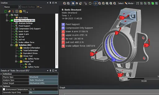
BOUNDARY CONDITIONS
& FOS
Before manufacturing, every component is subjected to rigorous FEA simulations in Ansys. We apply extreme boundary conditions to ensure that the required Factor of Safety is met under maximum simulated loading conditions, guaranteeing survival through endurance events.
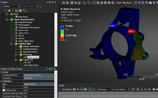
COMPLIANCE &
TOPOLOGY
Static structural heat maps allow us to identify low-stress regions. We perform topology optimization on every component to enable aggressive weight reduction without negatively affecting the part's stress limits or kinematic performance.